Basic Hydraulic Circuits
This post will give an introduction to hydraulics in order to build a small system and play with it.
Basic hydraulic circuits
Goals:
In this tutorial you will:
In this tutorial you will:
- Get in touch with hydraulic components.
- Make and modify connections between component ports.
- Play with different configurations using the given components.
Start by loading the system Tutorial: Basic hydraulic circuits into the workspace, and then navigate through the components in the tree and the scene to explore them.
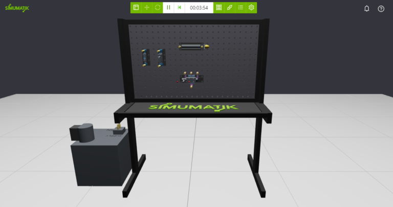
System description
The system includes an assembly consisting of a workbench with a hydraulic pump, a double-acting cylinder, a flow control valve and a manual 4/3 way directional valve.
Build a basic circuit
The first basic circuit you are going to build is the one represented in the diagram below.
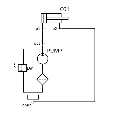
The hydraulic pump ‘PUMP’ will be directly connected to the double-acting cylinder ‘C01’. ‘PUMP’ has two hydraulic output ports called ‘out’ and drain, and you will connect them to ‘C01’ input ports ‘p1’ and ‘p2’ respectively.
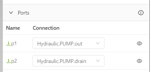
Start emulation
The basic circuit is now ready to test. We should expect that the cylinder will expand when the emulation is started. Click on start and see if it works.
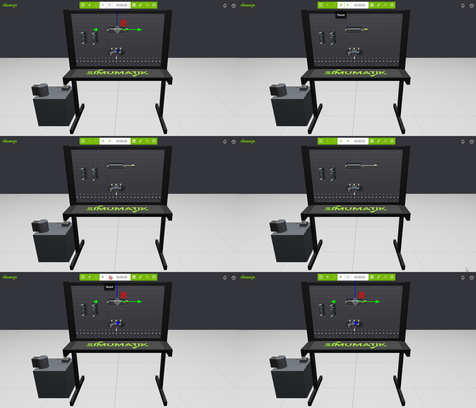
You can inspect the ‘PUMP’ and ‘C01’ port values to see that the values are transferred.
Note
In the case of hydraulic ports, both 'pressure' and 'flow' are represented in international units.
If you reset the emulation, the components will be reset and the cylinder will go back to its retracted position.
Note
In the case of hydraulic ports, both 'pressure' and 'flow' are represented in international units.
If you reset the emulation, the components will be reset and the cylinder will go back to its retracted position.
Modify the circuit
Note
Make sure you have paused or reset the emulation before you continue so you can modify the system.
Now we are going to add the ‘Y01’ 4/3 way directional valve to the circuit, between the ‘PUMP’ and ‘C01’ components so we can manually activate the cylinder when we act on the joystick of the valve.
Make sure you have paused or reset the emulation before you continue so you can modify the system.
Now we are going to add the ‘Y01’ 4/3 way directional valve to the circuit, between the ‘PUMP’ and ‘C01’ components so we can manually activate the cylinder when we act on the joystick of the valve.
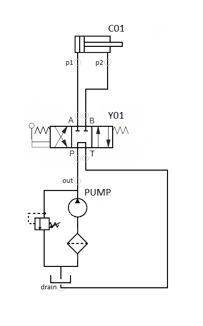
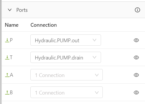
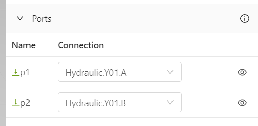
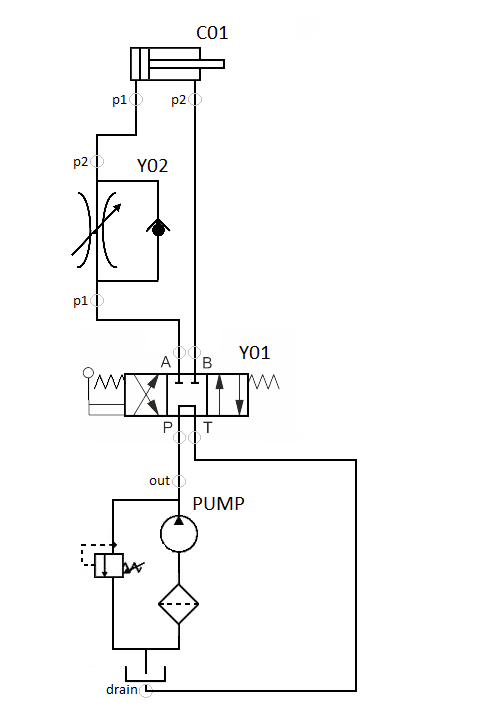
Connect the ‘PUMP.out’ port to the ‘P’ input port of the ‘Y01’ valve and ‘PUMP.drain’ to the ‘T’ port like in the diagram. Then connect the ‘C01’ input ports ‘p1’ and ‘p2’ to the valve output ports ‘Y01.A’ and ‘Y01.B’ respectively. ‘Y01’ and ‘C01’ port connections should look like the following:
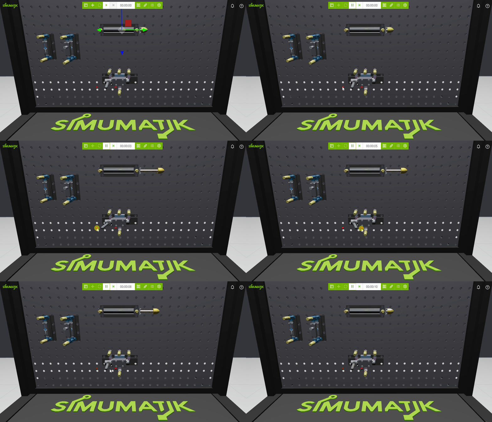
Start the emulation, you can press the red spheres on the sides of the ‘Y01’ joystick to move it left or right and command the cylinder.
Time to play!
Now it is time to play and build your configurations using the different components you have in the system.
Here you have an example. This circuit uses the flow control valve Y02 to make the cylinder extend slower, but retract with the same velocity as before.
Copyright © 2026

