
Building a Toy system
Build a basic system from start to finish.
Introduction
Building a system is at the core of the Simumatik platform.
A system can be defined as a set of interacting components. Behaviors and attributes set the rules for the interactions. This includes physical, electrical and mechanical attributes.
By running a system in a simulation
Simumatik emulates its real world behavior when running the system. We can view and analyze it as it would behave in the real world. A system grows from simple to complex, but the basic principles for building one stays the same. Components are placed, configured, connected and customized. The toy system you are about to build in this module may seem a little trivial, but the concepts are fundamental to anything you build in Simumatik.
Learning Outcomes
In this module, you will learn the basics of building a system. It is assumed that you have basic knowledge about how to navigate the user interface, as well as placing, connecting and configuring components. When finished you should be able to create a basic, non trivial system by yourself. You will learn to use component ports and how to control component interactions. The knowledge you get from this module is one of the core foundations of working with the Simumatik Platform, and you will have a great opportunity to further develop your skills in further modules.
The most basic system consists of simple objects that interact directly through their innate properties, such as physical interactions between objects. These systems may give valuable observations, but contain no logic and do not achieve anything.
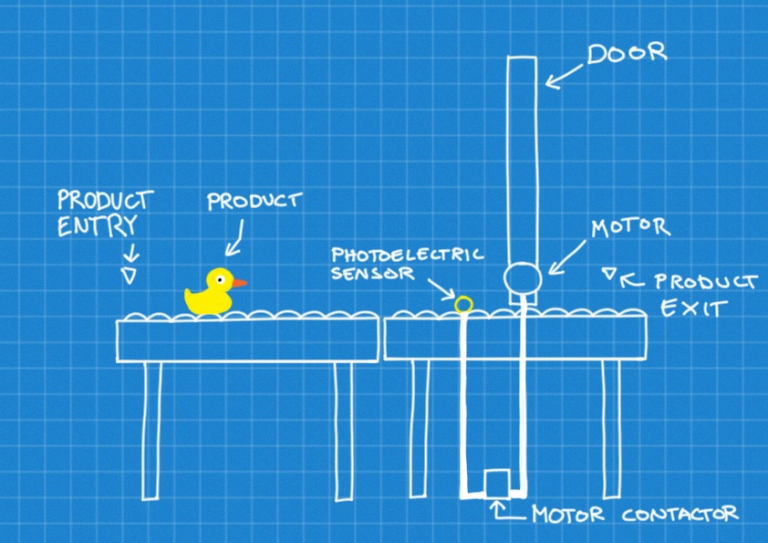
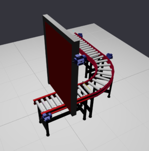
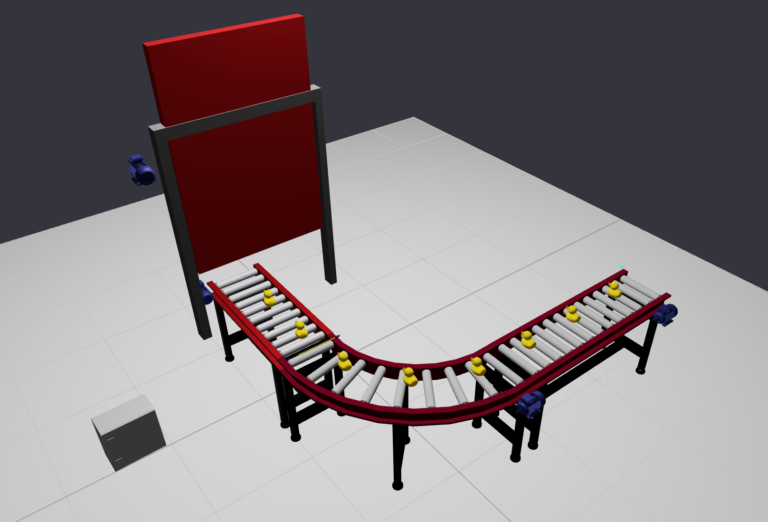
The system you are about to build needs to solve a problem. It consists of a set of conveyors where a product is transported. The path is blocked by a door, and we need to model the system in a way for the door to open, so the product can exit the system. To achieve this we use a photoelectric sensor that controls an electric motor that opens the door.
For basic knowledge about how to use the platform interface please refer to the manual. The exact positioning of the components isn’t important as long as the functionality is preserved.
Get an overview
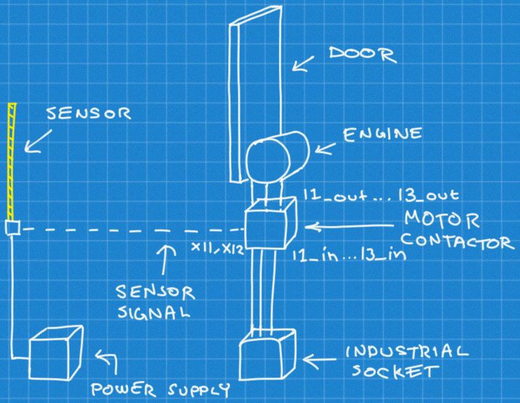
Look at the illustration above. Now lets start to build the system.
Look at the illustration above. Now lets start to build the system.
Conveyors
Conveyors are used to transport the products in the system. The standard library provides different types of conveyors and conveyor guides that can be combined to form a path for the products. The backbone of the Toy System is a set of conveyors used to transport the product.
Conveyors operate by the motor connected to the motor_axis port. Place two or three medium sized conveyors in a row and attach AC motors to each of them. Remember that ports can only have one input, so the connection needs to be done from the side of the connected component. The phases of the motors need to be connected to the industrial socket for power.
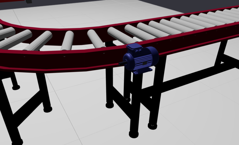
Electric motor connected to a conveyor.
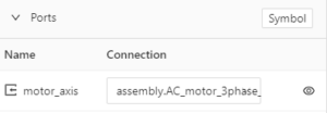
Conveyor motor axis port
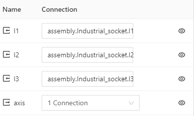
Motor industrial socket connections
Door
The door should physically block the conveyor when it is closed. Place it at the end of one of the conveyors as depicted in the blueprint and connect a motor to the door.
Product Entry and Exit
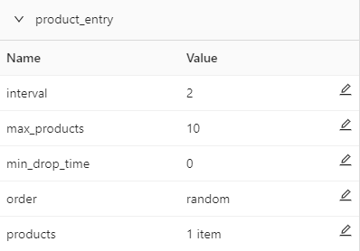
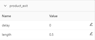
Products are objects typically used to represent something manufactured or handled through the system. Products enter the system at a specified point called product_entry, and exit through product_exit.
The product settings are reachable from the assembly menu and lets you set different parameters on which rate they will appear in the workspace, and a model representing them. Products are components themselves and may have attributes such as mass and different collision models.
The product settings are reachable from the assembly menu and lets you set different parameters on which rate they will appear in the workspace, and a model representing them. Products are components themselves and may have attributes such as mass and different collision models.
You have now created the physical infrastructure for the system. The next step is to add the logic
A new workspace in Simumatik is always empty from components. The only existing element is the floor, which handles collisions so that object doesn’t fall through. Several of the components need power to operate, which means we have to add power outlets for the different kind of power requirements the components of the system have.
The motors connected to the door and conveyors need power for torque. The photoelectric sensor needs power to operate, and the motor contactor needs electricity both for the control signal and power that it can relay to the motor operating the door..The standard library provides different components used to supply power.
For aesthetic reasons they may be placed in a electric box or similar container.
Power Supplies
The photoelectric sensor is powered by a standard 24V DC power supply. This is also used to control the contactor.
The photoelectric sensor is powered by a standard 24V DC power supply. This is also used to control the contactor.
The conveyors are powered by an industrial 3-phase socket. The socket also powers the electric motors.
Objective
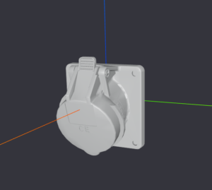
Place the 24 V power supply for the photoelectric sensor , and the 3-phase industrial socket into an electric box .
Photoelectric Sensor
Place the sensor in front of the door. You may have to try out different placements until you find one that is close enough to the door for the products to pass through. The sensor reacts when an element enters its view, represented by a yellow rod. It then activates and sends a 24V current through its signal port. It is powered by two ports, x1 and x2, that has to be connected to the DC power supply.
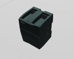
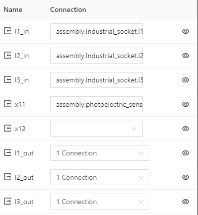
We use a motor contactor as an intermediary between the sensor and the motor. The contactor has five inputs and three outputs as shown here. The inputs are the three phases, I1_in … I3_in, and the ports x11 and x12 used to control the current flow.
We use a motor contactor as an intermediary between the sensor and the motor. The contactor has five inputs and three outputs as shown here. The inputs are the three phases, I1_in … I3_in, and the ports x11 and x12 used to control the current flow.
The input is routed to the outputs , I1_out … I3_out, depending on the control current on the ports x11 and x12, where x11 is connected to the signal port on the sensor. When the signal activates, the motor contactor delivers power to the motor.
The input is routed to the outputs , I1_out … I3_out, depending on the control current on the ports x11 and x12, where x11 is connected to the signal port on the sensor. When the signal activates, the motor contactor delivers power to the motor.
Breakdown of the steps in the model:
- The product hits the sensor.
- The sensor port signal outputs 24V
- The motor contactor reacts on the control signal and routes its input power to the output power.
- The engine receives power via the motor contactor and opens the door.
Run the system
Products enter the system and travel via the conveyors. When a product hits the sensor, the door should open, letting the product through. The speed of the conveyor may need to be adjusted in order for the door to open fast enough to let the first product to pass. Alternatively you can adjust the distance between the sensor and the door.
Conclusion and Further Studies
You have now built your first system from start to finish. Compared to an industrial system it is very simple, as are the components used. However the basic principles for building, connecting ports and modeling the interactions between components scale and you are now ready to work with more complex systems and components.
This is an exercise built to get experience working with the application and getting a feel for how systems work. It can be experimented with, by changing how the door is operated, for example through a PLC.
Currently, the door opens a little bit each time a duck passes the sensor. Can you modify the system to stop opening the door any further after the first duck has passed? Maybe try expanding the system by adding a second sensor that closes the door when activated?
As systems grow bigger, the need for structure increases. Simumatik has developed a set of guidelines and best practices to manage larger projects. The guidelines are described in another academy module and is the next natural step on your way to master modeling in Simumatik.
Copyright © 2026
Created with