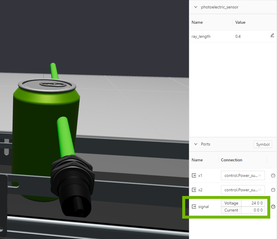
Electrical signals in Simumatik can be ordered in digital and analog signals. Digital signals can only have two states, represented with 0 and 1, off and on, or 0V and 24 V. The digital signals enables functionality such as a photoelectric sensor detecting an object or not. If the sensor detects an object the electric signal from the sensor will be 24 V, but if the sensor does not detect an object the signal will be 0V. Other uses for digital signals could be to turn a motor or a lamp on or off, or open or close a valve.
No detection: 0V
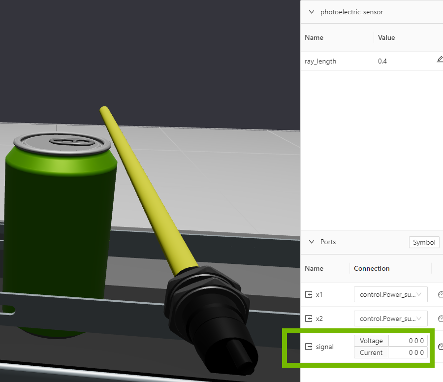
Object detection: 24V
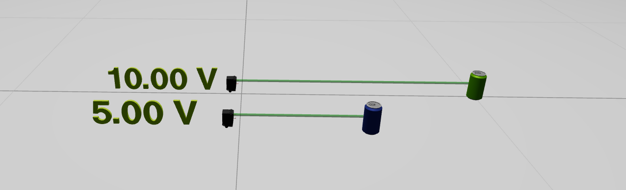
Analog signals, however, can have an infinite number of states. This is useful for example when measuring distances or tank filling levels. A analog distance sensor operates by measuring the distance to an object and converts it to a electric signal, where the voltage directly corresponds to the distance measured.
Lets say we have an analog distance sensor that has a measuring range from 0-1 meter and a electric range between 0 and 10V. In the image below we have two cases, one with a green can at 1.0 meter from the sensor and one with a blue can at 0.5 meters from the sensor. The sensor measuring the green can will output 10.0 V and the sensor measuring the blue will output 5.0 V.
The same example but letting the measuring range be from 0 to 12 meters, will give the following voltages:
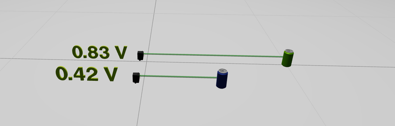
The output voltage from the sensor can be calculated as follows:
analog_range = voltage_max - voltage_min
voltage_output = analog_range*(distance/sensor_range_max)+voltage_min
The electric signal that carries the analog value can be read as an input to a component, for instance an analog input card to a PLC. To interpret that value the same technique with voltage range is used, and the following formula can be used.
value = (sensor_range_max-sensor_range_min)*(voltage_value-voltage_min)/(voltage_max-voltage_min)
In this part of the course we will learn how to connect a analog distance sensor to an analog input of a PLC and read the value in the PLC. Codesys will be be used as PLC environment, for more information about connecting Simumatik to a PLC, check out the
Gateway and Integration course where you would find tutorials for different PLC brands.
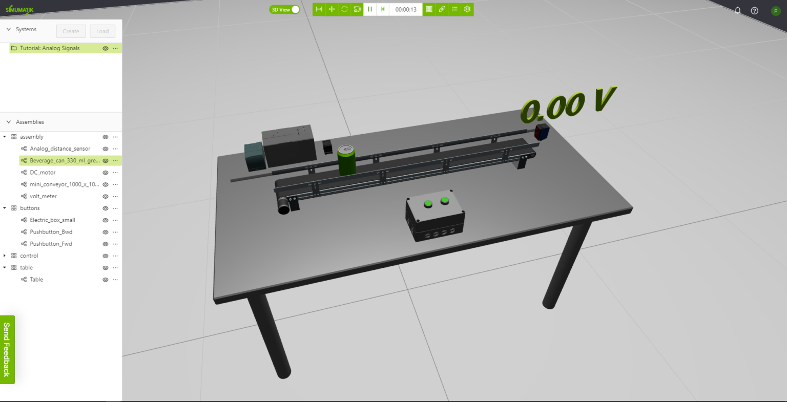
A Simumatik system called
“PLC Tutorial: Analog Signals” is available among the public systems. Load the system to a workspace. The system will look like this, it consists of a conveyor with a green can and an analog distance sensor along the conveyor to measure where the can is. There are two pre-wired pushbuttons that controls the conveyor.
Connect the sensor and the PLC to the power supply, and connect the sensor to Analog Input 1 of the PLC and the Volt meter. Now the voltage will be shown updated on the volt meter when the can is moved on the conveyor.
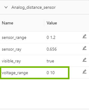
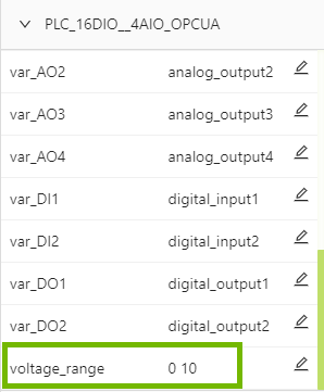
Make sure that the sensor and the PLC is set to the same voltage range. For example 0 – 10 V
Prepare a PLC program that reads the sensor_value and scales it to the distance value.
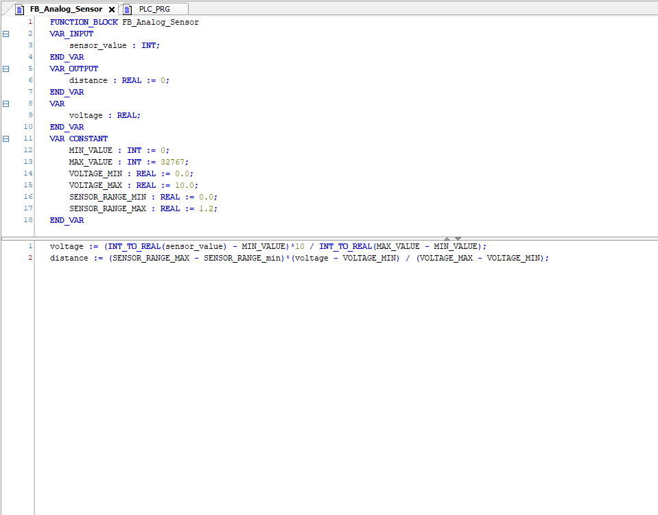
Connect the PLC and test the functionality that the distance value in the variable sensor_ray of the analog distance sensor is equal to the distance value interpreted in the PLC.